 |
'B21' panel(all documentation on this page below:) |
|
Wolfgang Piper (modelling, flight performance), Ian Forster-Lewis (gauges, programming, flight performance)
It's worth mentioning that this project was very much an extended iterative collaborative effort between Wolfgang and myself (Ian). He had all the good ideas and I made all the mistakes.
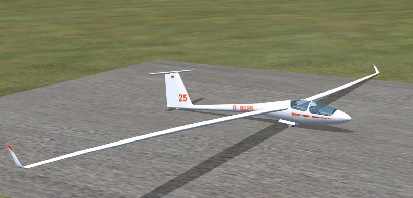
The ASH25 is a tandem two-seater high performance glider based on the world-championship winning single-seat ASW22. In the 26m wingspan winglet version modelled here, it has the highest glider performance available today with a maximum glide ratio of 60:1.
The ASH25 is designed for high performance. It has very high-aspect-ratio wings with six flap positions - negative for high-speed and cruise, zero for achieving the maximum glide, positive for thermalling, and a 'landing flap' setting to make landing this open-class racing aircraft slow and controlled.
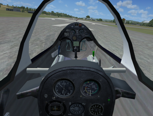
The ASH25, like all modern gliders, is designed to be fairly easy to fly. In this case that is particularly true once you've got the aircraft off the ground, where the long wingspan demands careful attention while rolling along the runway. Early-time glider pilots are helped if they gain some experience with an un-flapped glider, like the LS8-18 and then transition to the ASH25.
The most marked difference in flying technique of such a long-wingspan high-performance glider is that much of a cross-country gliding task should be completed without circling. I.e. the ASH25 is such an efficient flying machine that long distances can be covered with 'dolphin flight', merely 'pulling up' in each thermal. Also the ASH25 is extremely efficient at slow flying speeds (up to 80 knots, 130kmh) but above that threshold the efficient lift creation of the long wing introduces a significant penalty in the form of 'induced drag' (the drag that is an inevitable consequence of lift generation). Hence the negative flap settings are an essential feature to compensate for this vulnerability, and this also explains why 'open-class' (i.e. unlimited wingspan, like the ASH25) glider pilots pray for weak days in regional (mixed-class) gliding competitions when their phenominal max glide performance will really pay off. On consistently strong days a 15m glider will actually complete a cross-country task faster than an ASH25 by zooming at high speed between thermals and taking the strong climbs.
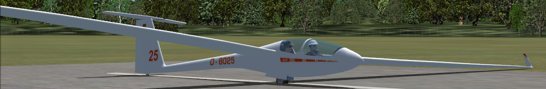
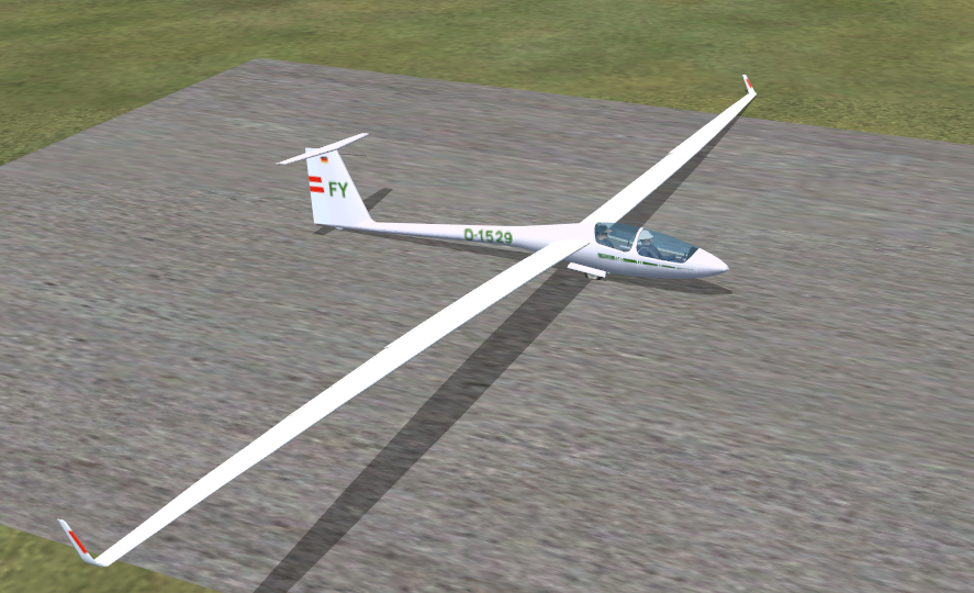
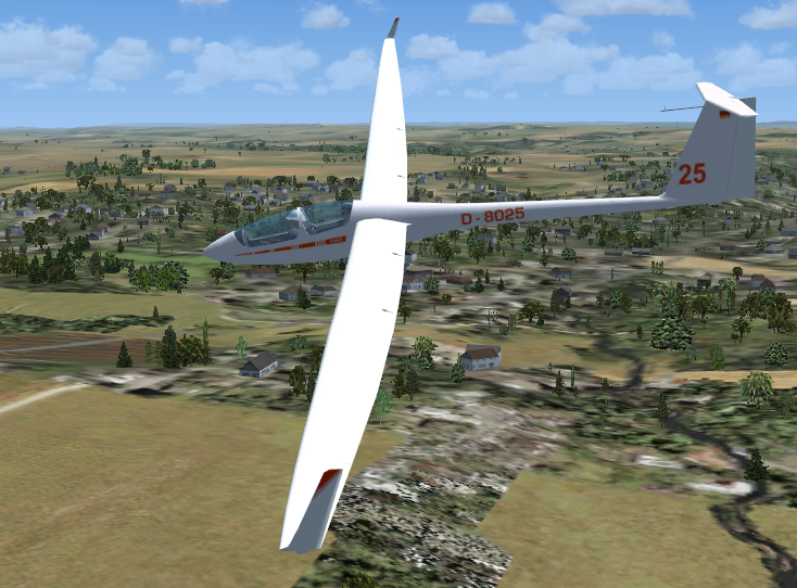
All three gliders have 3D cockpits for both front and rear seats, plus 2D cockpits for the front seats for those that prefer that. The glider has a full set of competition instruments. External views of the variants are shown below.
OK, so this feature could be oversold, but the fact is Wolfgang and I spent countless hours working on the wings. The end result is wings that behave reasonably sensibly in a variety of conditions. To me they're the most interesting on the ground and on the aerotow ground-run which I admit is a niche interest.
Perhaps uniquely in FSX, the ASH25 is an aircraft with a huge wingspan where the wings bend down so far when the glider is on the ground (and given the single mainwheel) it is normal for a wing to actually touch the ground. Getting this to look right isn't a problem large jet modellers have had to deal with.
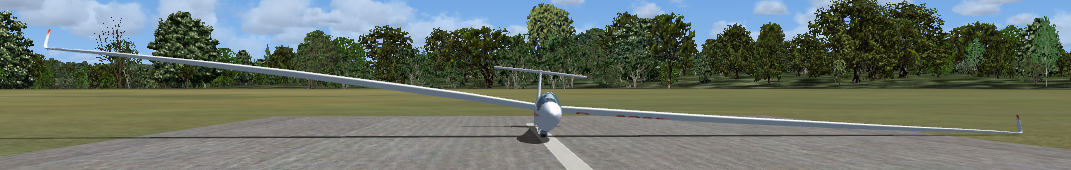
As the ground-run progresses, the wings steadily take the load and form the sweep you would expect in the air.

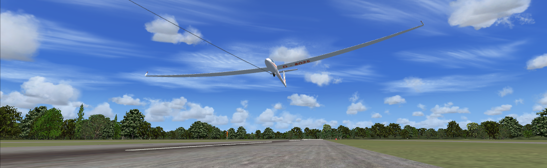
This picture below doesn't really show anything new but gives another angle. Perhaps here is a good place to mention that the ASH25 actually has pleasant handling characteristics and the take-off and landing is fairly straightforward. The tricky bit is the low-speed early part of the ground run, when the ailerons are ineffective but if you survive that bit the rest is easy. If you're new to soaring you can make the takeoff more manageable by taking off into a mild headwind blowing straight down the runway. A crosswind will be very difficult until you've got the hang of it.
|
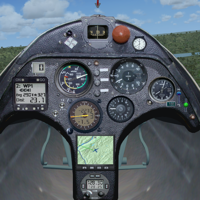
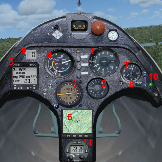
The 'B21' panel The 'B21' variant of the ASH25 has a competition-standard instrument set based around the Cambridge 302 Flight Computer. Variometer (compensated vertical climb) gauges show 'Total Energy', 'Netto' and 'Speed to Fly' readings concurrently. The '302' flight computer computes in real-time the optimal 'speed to fly' for the current conditions and moves its main needle to show the pilot whether it would be appropriate to speed up or slow down. A decimal display shows the expected arrival height at the current selected waypoint, particularly important on 'final glides' in such a high-performance glider. Combined with the GPSNAV (left side of the panel) and GPSMAP (bottom of the panel), the glider gives comprehensive information for the pilot to maximise cross-country performance. While previously seen in the LS8-18, the GPSNAV and GPSMAP have been upgraded - the GPSNAV now allows the user to select any waypoint in the flightplan and the GPSMAP can display the position of other aircraft. The 'B21' instruments including the yawstring are all 'XML' instruments, avoiding the use of compiled 'dll' programs, so the installation is complete after a simple drag-and-drop of the aircraft into the FSX folder. |
|
|
The view from the rear seat The rear-seat position is available via the 'Views/Cockpit/Rear Seat' menu option. As with the real ASH25, panel space is at a premium (and gauges are expensive) so only a limited subset are provided to the the rear-seat pilot. In particular the '302' or 'L-Nav' master gauge only appears on the front-seat panel, with the 'slave' vario repeated on the rear-seat panel. |
|
 |
|
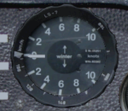 |
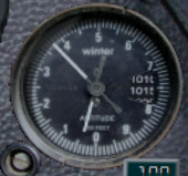
The Winter variometer main needle is displaying Total Energy compensated climb rate. This is simply your actual climb rate (or rate of sink) with small adjustments to compensate for changes in your airspeed which would otherwise affect the reading. |
When the pilot chooses to pull up to enter a thermal or to dive to exit a sink area, an uncompensated variometer would include the change in altitude due to the change in velocity in its read-out, thus obscuring the climb or sink rate due to the rising air. Therefore an uncompensated variometer can only accurately indicate the vertical speed of the glider when flying at constant speed. The effect of total energy compensation can easily be seen if you pull up into a climb in still air: an uncompensated vario will show a rapid climb rate, while the TE vario will correctly show you continuing to lose energy.
The indicated climb on an uncompensated vario is particuarly misleading as you pull up into a thermal - at this point the uncompensated vario will indicate a climb whether you're in a thermal or not so it is possible for inexperienced pilots to be turning and cimbing into a thermal that is not actually there. These have been called stick thermals as they are created by the action of the pilot pulling back on the 'stick'.
The action of diving or pulling up affects the speed of the sailplane. A sailplane can exchange height for speed or speed for height, i.e. potential energy for kinetic energy or kinetic energy for potential energy. In fact, in still air, the sum of potential energy and kinetic energy, i.e., the Total Energy, remains constant (neglecting energy loss due to drag), hence the name Total Energy compensation.
Most modern sailplanes are equipped with Total Energy compensated variometers.
The instrument automatically switches between m/s or Knots display depending on your FSX settings.
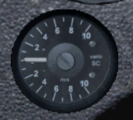 |
The needle displays NETTO climb rate (i.e. the vertical movement of the air outside the glider), by subtracting the normal aircraft sink rate from the total energy reading shown on the Winter vario. |
The Netto reading is a further refinement upon the Total Energy reading delivered by the Winter variometer. The Netto vario uses the glider airspeed to derive the sink rate the glider should be sinking at in still air at the current airspeed, and subtracts that from the 'total energy' reading. So the reading you're left with should be the net vertical movement of the air outside the glider.
Note that this FSX gauge is performing the same calculation that would be performed in a real glider gauge, using the input pressure sources (i.e. is it not 'cheating' by just reading some FSX vertical air movement variable). This means the gauge performs in the same way as a real gauge, e.g. if you open the airbrakes the gauge will interpret that correctly as unexpected sink. If you leave the wheel down, the netto vario will display sink even in still air, as it can tell the glider isn't flying at it's calibrated sink rate.
If you turn CumulusX off, and select 'clear weather', you'll find the Netto vario reads pretty close to zero throughout the range of normal flying. You'll see momentary dips into apparent sink as you manoever the glider (e.g. a pull-up) as it loses energy during that process. If you do a 'push-over' (i.e. fly as if going over a hump-backed bridge) the netto reading will correctly briefly go positive as the reduced loading on the wings results in temporarily improved efficiency at low speed.
The instrument automatically switches between m/s or Knots display depending on your FSX settings.
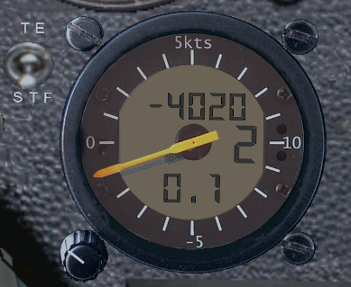 |
The main needle displays a Speed-to-fly indication (i.e. the needle moves down, as if indicating sink, to tell you to speed up and vice versa). The top numeric display is the expected arrival height AGL at the next waypoint in the flightplan. The middle numeric display (at 3-o-clock on the instrument) is the Macready setting. The bottom numeric display is the climb average. Heights are in feet, climb rates in knots, or meters and meters-per-second depending on your FSX units settings. The four readings (STF, arrival height, maccready, climb average) are explained in more detail below. |
This tutorial on speed-to-fly is taken from the LS8-18 information which remains equally valid in the ASH25.
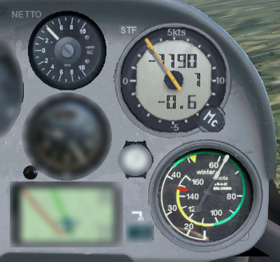 |
Speed-to-fly is yet another derived improvement in variometer compensation... In this image, the stf needle is indicating lift (as if +3 knots) meaning "you're in lift, slow down". You can see the Netto vario confirms this. At this point it would be reasonable to question the difference between a Netto and a Speed-to-Fly variometer, as they both appear to behave in a similar way (generally, needle up in lift, down in sink). But the difference is probably more marked than the difference between the Netto vario and the Total Energy vario (with a bit of luck you understand that difference). If you think of the Speed-to-Fly instrument as a variometer then the reading starts making sense in that it is taking some of the thinking workload off the pilot by indicating lift only when the you should actually slow down. i.e. pull up i.e. the lift has to be strong enough to exceed the MacCready setting and you have to be flying fast enough that slowing up is sensible. Counter-intuitively, you can fly through a little bit of lift and if you have a higher MacCready setting, and you're not flying fast enough, the STF needle will still indicate sink, i.e. speed up. Explaining this on paper is a poor substitute for flying with the instrument and getting used to its behaviour. At first you can just blindly follow its instruction, speeding up or slowing down depending on whether the needle is going down or up. But after a short while you get used to thinking of the instrument just as a particularly intelligent variometer, than doesn't bother you with lift if you're already slow enough. |
Given that the variometer is computing the 'Netto' movement of the airmass outside the glider, the vario can compute the optimal speed to be flying through this air. I.e. if you are flying through sink you should fly faster to spend less time in that sinking air, and vice versa for rising air. The faster the air is sinking, the more you should speed up.
The speed-to-fly reading is the delta between the computed optimal speed and the speed you are currently flying, displayed on the normal vario needle. If you are flying at the optimal speed then the needle will show zero. If the needle goes down as if indicating sink, then you should speed up.
A fully ballasted glider should normally be flown fairly fast (e.g. 90 knots) to benefit from all that ballast on board.
If you're flying too slowly (common for inexperienced pilots) then the STF indication will indicate sink i.e. speed up. As you speed up, the needle will return to zero as you reach the 'optimal' speed.
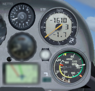
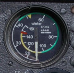
These instruments on the panel have a unique learning aid in the use of the Speed-to-fly indication: if you click the face of the ASI (i.e. airspeed) gauge, the real-time computed speed-to-fly is indicated with a red 'bug' moving around the rim of the ASI gauge. In the image above, the 'stf bug' is drawn on the ASI at about 92 knots. You will see the delta between this bug and the ASI needle is directly translated to the Speed-to-fly needle on the 302 computer vario. Also you can immediately see the effect other variables have upon the computed speed-to-fly, e.g. if you change the MacCready setting the speed-to-fly will change, or if you dump ballast then the speed-to-fly will gradually reduce as the ballast drains out.
Note the instrument has no knowledge of thermals ahead, and the reading does not take into account your 'pucker-factor' based on proximity to the ground, so if you're low and at risk of a landout you should not be charging around at 90 knots regardless of what the STF instrument is telling you to do... in this situation you should simply turn the MacCready down to zero.
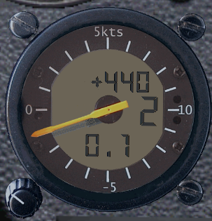 |
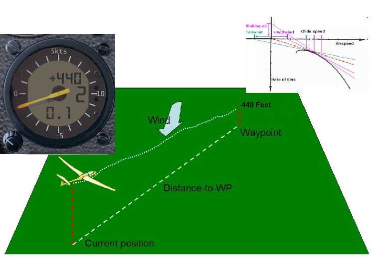
The flight computer will attempt to calculate your likely arrival height at the next waypoint. The simulated reading in the 302 computer vario is unusually sophisticated in that it gives you arrival height *AGL* (above ground, at the waypoint). In this case, the flight computer is suggesting you will arrive at 440 feet above the next waypoint. |
The graphic below illustrates a pilot gliding towards a waypoint, with the 302 vario indicating an arrival height of 440 feet (the real Cambridge 302 actually doesn't display arrival height at all, just an altimeter reading)..
The flight computer uses the elevation given in the flightplan (or the next point-of-interest in a mission) for the height of the next waypoint, and arrival heights are displayed relative to this. If you pick an airport as a waypoint in the flight planner then ground elevation is by default put into the flightplan. If you use some other waypoint type in the flightplan (e.g. an Airway Intersection) then the altitude of that waypoint will be embedded in the flightplan and the 'arrival height' computed by the vario will be relative to that. So for normal cross-country soaring purposes you should ensure the heights in the flightplan are ground elevations at each waypoint (or Zero if you'd prefer the arrival height indication to be MSL).
As with the FSX GPS, this indication is meaningless unless you have a sensible flightplan loaded in FSX.
The flight computer has to take into account a variety of factors to come up with a reasonable prediction of your arrival height, assuming a straight glide to the waypoint. These include:
You can view the same 'arrival height' reading either of two ways, which are actually equivalent:
You can use either of these definitions, whichever you're comfortable with.
As a reminder, the 302 flight computer vario is assuming zero overall lift/sink during this glide to the waypoint, that the wind remains constant at its current value (a headwind shown here) and that the pilot flies at a speed as appropriate to the MacCready setting.
More sophisticated flight computers, such as the SDI C4, can actually perform this calculation around multiple waypoints to the final destination, which is fairly complex, whereas the simulated Cambridge 302 shows arrival height at the next waypont only
|
The MacCready Setting is the value input by you, telling the vario the expected thermal strengths. In this case, you have told the flight computer to assume an expected thermal strength of 2 knots. Note that m/s will be used for this reading (in 0.5m/s increments) if metric settings are chosen in FSX. |
The value is adjusted using the knob at 8-o'clock on the LCD vario. Easiest is to hover the mouse over the knob and rotate the mouse wheel. The vario displays the MacCready setting in either m/s or Knots depending on your FSX settings.
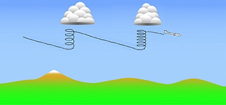
In the image above, the pilot has set a conservative MacCready setting and is flying relatively slowly between thermals and conserving height. This means she needs to climb less in thermals, i.e. saves time in thermalling (but is possibly losing time in the cruise).
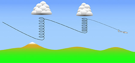
The pilot in this image has set a higher Macready setting, and is cruising faster between thermals. This means he has to climb more than the pilot that was cruising more slowly. Which pilot achieves the best cross-country speed depends on the strengths of the thermals (i.e. which pilot has guessed correctly in the Macready setting). If the thermals are weak, then the pilot that is cruising more slowly will achieve a higher overall speed because they are spending less time climbing in the weak lift.
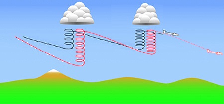
In this case, if we see the two flights superimposed, we see the more aggressive flying by the faster pilot has actually paid off, i.e. the thermals are strong enough that his additional height loss and need to climb is outweighed by the increased speed beween thermals.
Essentially the MacCready Setting is the value you use to tell the computer how aggressively (i.e. quickly) you want to fly, and the computer will perform its computations based on this value. For a fully-ballasted ASH25, a MacCready Setting of 3 knots (1.5m/s) will mean you should be flying at about 90 knots between thermals. The idea is simply the stronger the thermal you expect, the faster you should fly to get there. This is well explained in the "Art of Flying" last video in the sequence on this page.
|
This shows a moving average of total energy climb/sink in either Knots or m/s depending on FSX units settings. In this case the computer vario is recording an average climb rate of 0.1 knots. |
When you are thermalling, this displayed value can guide your judgement on what to set for the Macready setting. Also, if you are thermalling, if this average is below the readings you have typically seen in other thermals on the same flight, then perhaps you should leave the current thermal and find another.
This average will also give you a clue that the thermal strength is weakening near the top of a climb, and you should leave the current thermal rather than milk it to the top.
The switch can be seen in the top-left corner of the image above.
This switch changes the main needle indication on the 302 Cambridge vario from 'speed-to-fly' to a 'total energy' reading, the same as that on the Winter vario. This makes sense before you've crossed the start line on a cross-country task, where maximising cross-country speed is irrelevant and you're more concerned about climbing in the area of the start airfield to get well placed for a good start.
In TE mode, the needle shows total-energy climb rate as described above, but the 302 will also show speed-to-fly push-pull arrows at 12-o'clock or 6-o'clock to tell you to slow down or speed up respectively.
|
As seen on all aircraft, the ASI displays airspeed in either Knots or km/h depending on FSX settings. |
This instrument in the ASH25 includes a speed-to-fly training aid made visible by clicking on the face of the dial. See information above under 'speed-to-fly'.
|
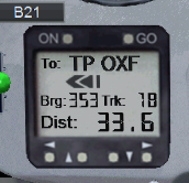
The GPSNAV shows the direction and distance to the next waypoint in the flightplan. For the GPSNAV to display something sensible, you must have an FSX flightplan loaded. The moving map will display the flightplan. |
The GPSNAV is similar to the stock FSX DG808S gpsnav with various improvements made to improve readability. More significantly, the internal 'GPS' engine has been re-written to replace the original programming, so the pilot can step forwards and backwards through ALL the turnpoints in the task by using the 'up' and 'down' buttons.
Details on the home page are as follows:
The distance-to-go units (miles, km) depends on your FSX setting. You can click the 'left' and 'right' buttons on the GPSNAV to see another couple of pages of information (waypoint info) but these are less useful than in the real GPSNAV to make sure you've loaded the right flightplan, because in FSX you can just look at the moving map or use the FSX menu.
The GPSNAV 'page' you see displayed above is the 'Home' page of the GPSNAV, and it the one used for normal flight around a task. Any waypoint of the task can be chosen to be the current 'active' one by using the 'up' and 'down' cursor buttons while on this home screen. To gain familiarity with the instrument, try these buttons while you're still on the ground.
The GPSNAV will automatically select the next waypoint in the current flightplan to be 'active' when you are within 500 meters of the current waypoint. However there is nothing to stop you overriding this behaviour at any time simply by using the 'up' button to move on to the next waypoint. An example of where this might be useful would be in a start of a task, where you know the start line allows you to be a lot further than 500 meters from the start point, but you still want to have the GPSNAV move on to the first TP even though you haven't passed 'through' the start point. Also, many FSX soaring flightplans have the home takeoff airfield as the first waypoint in the flightplan even though it isn't actually the start point of the task, and one click of the 'up' button will put things straight ready for your record-breaking competition flight.
In some circumstances, you may wish to keep the GPSNAV pointing at a waypoint even though you have moved within 500 meters of it and the gauge has clicked over to the next, e.g. you've done a poor start and want to start again. In this case you can simply re-select the start waypoint by using the 'down' arrow. The usage is intuitive and obvious if you just try the 'up' and 'down' buttons.
If you use the 'left' and 'right' arrow buttons, the GPSNAV will cycle through a couple of other 'pages' of information about the current active waypoint. This is only marginally useful in the air, although one page contains the elevation of the active waypoint (labelled 'EL:') and this is useful to check the 'arrival height' being presented by the 302 LCD computer as this arrival height value is above this elevation given for the waypoint. Normally the elevation for the waypoint will be the ground elevation, so the 302 arrival height reading will be what is commonly referred to as 'AGL' (above ground level).
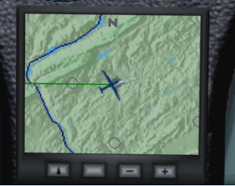
The 'Moving Map' GPS is fairly intuitive with limited user options.
You can zoom in/out using the +/- buttons.
The 'up arrow' button (left) toggles the map between 'north up' (as seen in the image above), and 'track up' as in the image below.
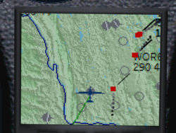
The unlabelled button to the right of the 'up' button actually toggles the visibility of other aircraft in the map view (as you can see in the image above), useful if you are flying on multi-player and want to keep track of your flying friends.
The current leg on the flightplan is shown with a green line, the others will be red.
This is a standard static-pressure-driven altimeter, that switches units from feet to meters in FSX depending on your FSX units settings.
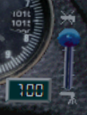
The small LCD display on the panel displays percentage of water ballast carried. Broadly, full water ballast increases the weight of the empty glider by 50%. Modern competition gliders carry jettisonable water ballast (in the wings and sometimes in the vertical stabilizer). The extra weight provided by the water ballast is advantageous if the lift is likely to be strong, and may also be used to adjust the glider's center of mass.
Click the top or bottom of the blue-knob gauge to open/close the ballast valves.
The LCD ballast indicator has a configuration aid for FSX to help in transplanting the gauge into another glider. If you click the face of the ballast indicator gauge it will display the current all-up weight of the glider in Kilograms. As you dump ballast you'll see this figure reduce.
Although heavier gliders have a slight disadvantage when climbing in rising air, they achieve a higher speed at any given glide angle. This is an advantage in strong conditions when the gliders spend only little time climbing in thermals. The pilot can jettison the water ballast before it becomes a disadvantage in weaker thermal conditions. Another use of water ballast is to dampen air turbulence such as might be encountered during ridge soaring. To avoid undue stress on the airframe, gliders must jettison any water ballast before landing. (ref wikipedia)

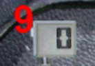
This gauge tells you your current flap setting. By default, the F6 key will move the flap lever forward (for higher speeds) and the F7 key will move the flap lever backwards (to extend flaps for slower speeds). The six available settings for the flaps in the ASH25 are (from 'slow' to 'fast' flight):
The GREEN knob on the far right side of the panel is TRIM, i.e. the 'neutral' setting of the elevator. 'Trim forward' will bias the glider into more of a nose-down attitude and at a neutral stick position the glider will fly faster, and the reverse for 'trim back'. You adjust trim using the default keys in FSX, worth assigning to buttons on your joystick. In general you 'trim forward' while in cruise between thermals, and 'trim back' when you pull up and turn into a thermal. The idea is simply to have the glider settle into the appropriate default speed for the situation without you constantly pulling or pushing on the stick.
This ASH25 includes a TriggerTrim function (as a hidden gauge on the panel) inspired by Peter Luerken's TrimWizard. When you press the trigger on the joystick (i.e. activate the brakes) the trim will immediately move to the position of the stick. I.e. to trim forward, push the stick forward and press the trigger, and you'll see the green indicator move up accordingly.
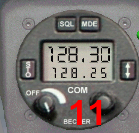
This is an airband radio