..this is a work-in-progress...
There are multiple parameters of an XPlane glider you have to tweak to get accurate flight performance, and the most important of these is the characteristics of the airfoil.
XPlane provides a tool called Airfoil Maker that allows you to customise the characteristics of your glider's wings.
In XPlane's Plane Maker (not Airfoil Maker) you specify airfoils for each 'wing' of the aircraft, including the horizontal stabilizer, the fin (aka vertical stabilizer) and the main wing. But the characteristics of the main wing are by far the most important.
'Designing' the airfoil for an XPlane glider is not quite the same process as needed by real glider designers as you are specifying the fundamental parameters affecting the performance of the airfoil i.e. you are not necessarily constrained by its shape. If you want to give your airfoil zero drag, then that's possible.(Note: it is possible to use industry airfoil analysis tools such as XFoil where you give it the shape and that software produces a performance file that XPlane's Airfoil Maker can ingest - more about this later but in summary this isn't very useful for gliders.)
So the real artistry is manipulating the parameters that XPlane offers to get the airfoil to achieve the correct Lift/Drag behaviour across the speed range (polar) and also get the low-speed area down to the stall reasonably authentic.
The method is to get the airfoil reasonably correct, then fly the aircraft in XPlane while measuring the L/D ratio (this means studying the relevant airspeed / sink rate datarefs) and check that against the documented polar. Then tweak the airfoil parameters small amounts aiming to nudge the performance in the direction you want. When you've got the polar accurate you can then work on the high Alpha / low speed / stall regime by tweaking parameters while trying to keep the more regular flying characteristics unaffected.
Steps 1-9. Read the XPlane Airfoil Maker manual.
We'll use an example of an airfoil created for the ASK21. It's not perfect but illustrates the concepts. The airfoil source file is B21_ASK21.afl.
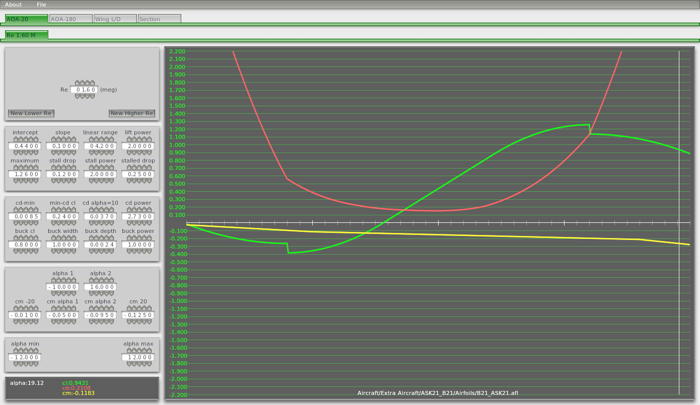
Opening this file in XPlane's 'Airfoil Maker' (available in the XPlane main program folder) takes you immediately to the window showing you the defining parameters and allowing you to adjust them (once you have a clue what you're doing...). Note that all the adjustable parameters are on this page - there are additional tabs but they give you similar graph displays of the performance rather than being the data 'entry' pages.
The X-axis of these graphs is Alpha, i.e. the angle-of-attack of the wing with the tick marks illustrated below being -20, -10, 0, +10 and +20 degrees. While not complex, it is essential you understand this concept. When the glider is flying slowly it will be nose-high, i.e. the main wing will be at a high angle of attack. When cruising at high speed the pilot will be pushing the nose down with the control column and the main wing will have a negative angle of attack. The marked center of the x-axis is for an angle-of-attack of zero degrees. So the simplest view is that these graphs represent slow flying speeds on the right of each graph (positive angles of attack) and high flying speeds on left (negative angles of attack). This angle-of-attack is through the air, not relative to some ground horizontal. At certain speeds the angle-of-attack becomes self-reinforcing, i.e. as the glider slows nearer to the stall the efficiency of the wing declines and the glider descent rate increases - this on its own will have the effect of increasing the angle-of-attack. In summary, analysis of an airfoil is, for example, Lift vs. Alpha rather than perhaps the obvious thing you'd first think of which would be the lift produced at different speeds.
The wing will be most efficient (i.e. Lift divided by Drag) somewhere around an Alpha of zero. In high-speed cruising the Alpha might be, say, -3 degrees, and slowing down into thermalling may bring the angle of attack up to +4 degrees. So for the normal performance range of the glider it is critical that you get the curves accurate across this range (-3..+4 Alpha).
The further negative range of Alpha on the graph doesn't matter much (how often do you do an inverted loop?) and the accuracy of the positive range beyond say +4 degrees isn't hugely critical except in designing the stall which will occur at an Alpha somewhere around +7..+13 degrees (your mileage may vary).
Here is a summary explanation of the input fields in Airfoil Maker. It is not a substitute for the thorough study of the XPlane Airfoil Maker manual.
As mentioned, the x-axis is always Alpha. The three curves on the graph represent Lift vs. Alpha (cl, green), Drag vs. Alpha (cd, red), and Pitch Moment vs Alpha (cm, yellow).
There are five gray boxes down the left side of the graph with sets of numbers you can adjust.
This is an indirect way of saying in which air density / airspeed regime this airfoil data will be used. A figure of 1.6meg is reasonable for a glider which operates in a relatively benign altitude and speed range nowhere near Mach 1 and this figure is not really critical. For more detail search the interwebs.
These input boxes control the green Lift vs Alpha line on the graph.
The numbers given in this example are a reasonable starting point for a modest-performance fibreglass glider. The parameters, such as 'intercept' and 'slope' directly control the Lift vs. Alpha curve on the graph (you see you are modelling the performance of the airfoil, not the shape). For example the 'intercept' is the cl value at zero Alpha. Just click the up/down buttons a few times on each input field and you will see how you can adjust the shape.
The first thing you will want to do is get the max L/D ratio for your glider to be the right value, at the right speed. you can improve the L/D by increasing lift of the wing (move the green line up) or reducing the drag (mode the red line down, see below).
After a number of trial flights in your glider while studying and noting the speed and sink rate figures, you may want to increase/decrease the glide ratio (or sink rate) in the higher airspeed or lower airspeed parts of the polar - remember this equates to lower Alpha / higher Alpha respectively. For example, to reduce the sink rate at the higher speed end of the polar you want to increase the lift, i.e. green line, at the low Alpha area of the graph. Ideally without moving the critical middle area of the graph at all. This takes careful juggling of parameters and with a small amount of practice you learn which other numbers to tweak a bit to keep the center on track while you mess with the high speed / low speed bits of the polar.
As an aside, although we're in the 'lift' section of the parameters here, to improve glide performance it can be more accurate to reduce the drag (see below).
I would recommend you get the polar accurate by adjusting both the lift and drag parameters before you circle back and spend time evaluating the stall (high Alpha) area of the Lift and Drag curves. In summary the 'stall power', 'stall drop' and 'stalled drop' parameters control how severely the lift drops off at some angle of attack. In particular the 'stall drop' parameter defines a sudden loss of lift at some Alpha (in the example, at about 11 degrees). These parameters are really useful for getting the stall right but take a lot of experimenting.
when you think you've nailed the low-speed high-Alpha performance of your airfoil, try thermalling your glider in tight turns, and also do a high-speed dive followed by a sharp pull-up. Both these things generate high-Alpha and it is almost guaranteed on your first effort your finely honed airfoil will dump you into a sharp stall and you'll have to go back and make your stall characteristics a bit more rounded so that it works across the range of normal glider flight.
Hopefully you're on a roll at this point and have your number juggle / test flight regime all working effectively. Tweaking the drag is similar but simpler than the lift curve and obviously lower drag is less sink, higher L/D.
This is the tendency (i.e. rotational moment) for the wing to try and pitch up (or down) at different values of Alpha. For practical purposes it's not too critical so long as you start with something broadly sensible like in the example graph.
Nearer the end of your testing you can tweak these figures to improve the pitch stability, i.e. a strong increase in upward pitching moment as the Alpha increases is going to make the aircraft feel twitchy in pitch so that's what you're adjusting here.
These are a simple pair of parameters which squish the Alpha (i.e. the x-axis) left and right - try them and see.
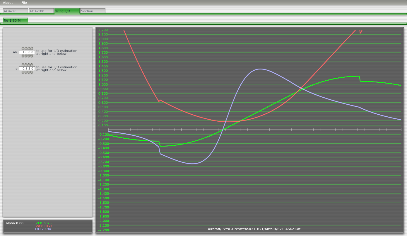
Of the other tabs, probably the most interesting for gliders is the "Wing L/D" tab this is the lift/drag ratio of the wing which for fairly simple reasons is exactly equal to the glide ratio of the wings (look this up on the internet if interested).
Of course the glide ratio of the main wing dominates the performance of the glider overall as the rest of the aircraft can be considered mostly ballast plus additional drag.
Aircraft-Airfoil Database is a useful online reference to find the name of the airfoil used on a particular aircraft. Then you can look up the data on Google or Airfoil Tools below.
ASK21 airfoil data from the Airfoil Tools website.
Sample X-Plane glider airfoils:
... more coming soon...